To calibrate the system you need to have a reference scale such as,
for example, a micrometer scale 1mm long with 100 subdivisions, or a metallographic
Vickers test with known lengths of the diagonals of indentation.
If the program is used by personnel not authorized to modify the system
calibrations, a security password needs to be activated.
To activate the security password, select Measure
menu->Change Password.
To calibrate an objective, follow this procedure:
get a reference scale, e.g., a micrometer scale 1mm long with 100 subdivisions (if the videocamera is installed on a microscope);
select a value for the Current Objective corresponding to the used optics;
open the video channel and align horizontally the reference scale with the field of view;
capture an image;
from the Measure menu select the Calibration function. Two vertical lines will be displayed with one horizontal line to check the horizontal alignment of the reference scale;
press the left mouse button to select the vertical line to be moved and position it on a point of the reference scale;
position the other vertical
line on another point of the reference scale and click the right mouse
button.
![]() To reduce to a minimum the possibility of error, select
two points on the reference scale as far away from each other as possible;
To reduce to a minimum the possibility of error, select
two points on the reference scale as far away from each other as possible;
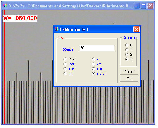
select the unit of measure (X-Vick requires the micron);
select the desired number of decimals;
insert the numerical value corresponding to the distance between the two points mentioned above and confirm by pressing OK.
The calibration of the current objective is completed and will be automatically stored.
Repeat the calibration sequence for the other system optics.
IT IS IMPORTANT TO FOLLOW THIS SEQUENCE:
select the objective;
acquire the image;
perform the calibration.
![]() Select the objective and acquire
the image, not vice versa.
Select the objective and acquire
the image, not vice versa.
![]() The calibration data are associated
with the images when these are saved. So, for every image saved, a file
is created having the same name as the image but with the ??0 extension.
For example, if the Image.bmp image is saved, an Image.bmp file will also
be created containing the calibration data and the information entered
in the Image
Info dialog box.
The calibration data are associated
with the images when these are saved. So, for every image saved, a file
is created having the same name as the image but with the ??0 extension.
For example, if the Image.bmp image is saved, an Image.bmp file will also
be created containing the calibration data and the information entered
in the Image
Info dialog box.
To change the calibration of a saved image, load the image and press
the Current Objective button in
the Image Info
dialog box.
The calibration in the vertical direction is automatic but may be modified in the following way:
if a WDM-compatible analog or digital camera is used, use the calibration for WDM procedure;
if instead the images are acquired with other non-square pixel devices, it is necessary to change the "YCorrection=1" value in the GAUGE.INI file present in the (C:\Programs\Alexasoft_X-Pro) application folder.
|
|
Extracted from the GAUGE.INI file |
|
|
[SetUp] YCorrection=1 XCalibrate0= XCalibrate1= XCalibrate2= XCalibrate3= |
Once the horizontal calibration is performed, rotate 90 degrees the reference scale and acquire a new image.
From the Measure menu or through the X-Vick measuring graticules, measure vertically the same tract of the reference scale. If the image has been acquired with a square pixel device, the vertical measurement will be equal to the horizontal one. If instead the measurements differ by an unacceptable quantity, a new YCorrection value will have to be calculated.
Horizontal and vertical tracts being equal,
let us suppose that the horizontal measurement is 100 microns and the
vertical one 85 microns.
The new value for YCorrection will be 100/85= 1,176
Then close the program, open the
GAUGE:INI file and modify the YCorrection value. Save the file.